Saturday, January 10, 2015

Checkpoint Lab - 4 (Installing Gaia R 76, Firewall gateway) Tutorial

Security Gateway install and setup

It’s pretty much the same steps and follows the same process as you did earlier for manager. I am just going to highlight the key differences in the below screenshots.
Since this is a gateway and we will log the traffic accept/reject and other parameters I would recommend you to change the below options instead of accepting the defaults and finish the installation.


This is firewall in main office, so it would have 3 interfaces (Refer the lab setup – Checkpoint – 1) internal network eth1, DMZ eth2 and external eth0. So during the setup config only eth1 and leave the GW empty. Firewall gateway would actually be the external ISP router. I will cover that later. We can always update the IP's later once we connect to either manager or gateway via browser. So if you make a mistake in assignment or miscalculate don't worry you can fix it. Just make sure until you can update remember the ip that you are assigning now.
If you are following the lab setup  - Select eth1 and assign 10.1.1.222
After the install you will be able to access the firewall with https://10.1.1.222 if you are following the lab setup.

STOP---IMPORTANT---CHECK

Select the “Security Gateway” Option.
The manager and firewalls talk to each other using SIC – secure internal communication method so you need to specify one time password for now. Later you will be using the same password to setup manager to gateway relationship.

Checkpoint Lab - 3 (Installing Gaia R 76, Manager) Tutorial

Management server install and setup

In a distributed check point deployment scenario the management server blade is installed as separate entity which will be then configured to connect to the firewalls using secure communication. Management server as name suggests is used to manage the firewalls centrally. We can set up rules, create users, NAT’s ECT on the management firewall, save it as a policy and push them to the firewalls. Other tasks like backups and restores can be performed as well.
Installation – Once you boot of from the ISO image downloaded (mentioned in earlier post), with a new vm (Memory 2GB, Processor1, HD – 40 GB, Network – Net2) follow the below steps

Once you boot off the ISO we can see the below splash screen…Choose Install Gaia on this system. Use TAB key to navigate options.
 It’s going to load the drivers…


 Hit ok to proceed with the installation… and follow the screenshots below...

Since this is Management blade and it’s connected to Net2 (10.1.1.0/24) input the ip in that range my case I choose 10.1.1.150 and the Gateway for the management blade will be the firewall’s eth1 interface which is 10.1.1.222. Refer to the example lab diagram @ Checkpoint – 1 Lab setup 
 And Reboot after completing the 6 steps.


Initial Configuration

We can access the Manager via browser from Client A (10.1.1.100) or this can be done via command line interface which I will cover as alternate initial config section later. Since we used 10.1.1.150 as our manager ip access this via - https://10.1.1.150. As soon as you login you will be presented with “First time configuration wizard” as below.


Set date and time, this is very important in production live environments and best practice is to use the companies NTP server. Policy sync’s, backups and many more checkpoint functions depends on having correct time across all the devices, checkpoint clusters.


Input host name, domain and DNS server info…I am using google and verizon public dns.


STOP---IMPORTANT---CHECK

The below options will configure the device as manager or the gateway/firewall.


Select – Security manager. I will cover clustering at a later date.


The below options will let you configure which device can connect to the manager. Std. security practice is one would restrict access to the manager to certain set of devices/jump boxes for better security. You have an option to select Client A 10.1.1.50 only, Any machine in Net2 network or certain range.

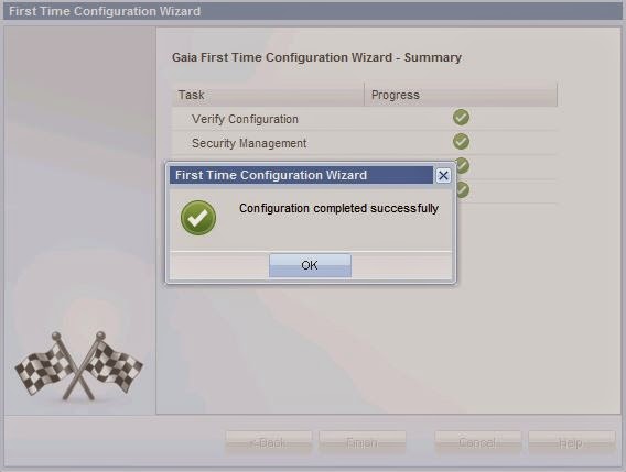
Finally verify and confirm that the right option – Security Manager is indeed selected and finish the initial config of manager. Again we use the manager to connect to firewall/Gateway devices at multiple locations for ease of management.
This concludes the installation and initial configuration of security manager in the lab environment.

Friday, January 9, 2015

Checkpoint Lab - 2 (Lab setup details) Tutorial

General discussion - 

When you have multiple firewalls/sites it make more sense to access and control them from a central location. That is the reason distributed model is preferred in large environments. In our lab example we use management server to connect to main office fw and branch office firewall.
In the distributed model the components involved talk to each other in a hierarchy model. 
  • SmartConsole ==> Manager ==> Firewall (create policy, rules, user id's)
  • Firewall ==> Manager ==> SmartConsole/View/Tracker (Logs, session info, license info ect.)
Any firewall should and will support the below 3 functionalities.
  • Packet Filtering
  • Stateful Inspection
  • Application Awareness
Packet Filtering is pretty straight fw. You can define what ports can come in and go out. Used to control access to and within your internal network.
Stateful Inspection is a method when the return /reply traffic is allowed to flow back. Example - Behind the firewall you access google.com assuming firewall allows port 80 and 443 outbound your request is sent to google server. The google server responds back to your request. Now you don't have to allow or create to accept the traffic from google since you initiated the connection in the first place. Firewall tracks that you make the request and will allow the traffic from google back in, it dynamically allows the traffic flow back in.
Application Awareness is gaining more prominence now a days. Consider the scenario, you allow traffic on port 443 outbound but deny ftp port 21 outbound. One way this rule can be circumvented is when you encapsulate the ftp traffic with https traffic and send it out. Firewall will honour that rule which defeats the purpose of having the firewall in the first place. So application awareness feature inspects the traffic at Layer 7 level of OSI model and will figure out that its actually ftp traffic and deny it. (Which is pretty cool)
Does not matter which firewall you choose (Sonicwall, Fortigate, WatchGuard, Barracuda) the above 3 would remain same or better vendor to vendor. NextGen firewall, UTM (Unified threat machines) lot of jargon thrown out there now a days but basically they are all same in my personal opinion. new bell's and whistle's, redesigned GUI, graphs....(Again I am not an expert but that is my take)

OS version info for checkpoint - 
Checkpoint website is the best place to get the latest firmware/OS information duuh..But just for information sake
IPSO was initial OS that checkpoint offered. (Never saw it or worked on it, if interested pls google)
SPLAT - Secure Platform was the first OS I saw from checkpoint.
GAiA - was released on 2011-2012 is basically hardened version of the above 2 OS combined with ipv6 and other improvements. For lab set up I am using GAiA R76.

Checkpoint Lab -1 (Lab setup details) Tutorial

Setup Check point in distributed environment (2 sites)

Distributed environment is where we make a design decision to install the checkpoint blades separately and connect them like security management server (SMS), security gateway ETC. I would recommend folks to google and gain insight on what is a distributed & Standalone deployments are? What are pros and cons? What checkpoint recommends?

Lab setup VMware workstation 9 – The lab set up would look something like this –
Hardware - 2 client machine, One VM for manager, 2 VM’s for gateway (firewall – 2 sites main office and branch office) , 2 servers/machines capable of supporting  ftp, ssh, web site (very minimal HW requirement, this is just to test )

Network – The client and the manager @ Main Office (Net2), DMZ 1-Main Office (Net2), DMZ 2-Branch Office (Net4), Branch Office (Net3), client @ Branch office(Net5), external routing  ISP we can use our existing internet home connection (Net0).

I used Gaia R76 the iso can be downloaded from checkpoint website. Usually checkpoint provides 15 day evaluation with all features. But if your company has checkpoint firewall you can reach out to your rep and they would help you to get an extended license for 30 days or so.


VM Build – 
  • Both the client machine I am using is a win7 machine, 2 GB RAM, 1 Processor, HD-40 GB, Net2
  • SMS will be installed via ISO downloaded previously, 2 GB RAM, 1Processor, HD-40GB, Net2
  • Main office Security Gateway is installed via ISO as well, 2 GB RAM, 1Processor, HD-40GB, Net2, Net5 & Net0.
  • Branch office Security Gateway is installed via ISO as well, 2 GB RAM, 1Processor, HD-40GB, Net3, Net4 & Net0.
  • First server I am using is a Win 2012 evaluation machine, 2 GB RAM, 1 Processor, HD-40 GB, Net4 (FTP, SSH and IIS).
  • Second server I am using is a Win 2012 evaluation machine, 2 GB RAM, 1 Processor, HD-40 GB, Net5 (FTP, SSH and IIS).
  • Net0 – ISP public access – 10.100.100.0/24
  • Net2 – 10.1.1.0/24
  • Net3 – 172.16.1.0/24
  • Net4 – 172.16.2.0/24
  • Net5 – 10.2.2.0/24
Snapshot of what my Virtual network editor looks like - 

Note – since these are actually VM’s in virtual environment you can use one server and flip the Net4 and Net5 to test scenarios from the client machine and below is the summery of networks I created for this lab scenario on the VM.


Thursday, April 24, 2014

One arm vs. Two arm load balancing.

Two arm - in line mode - Routed mode In this senario the clients and the servers are in 2 different networks (2 arms) and can talk to each other via load balancer which sits between them - inline. Clients are front end, servers are back end with load balancer in between. In most of the cases the backend servers have the load balancer as their gateway and the source or client ip can be preserved.

NOTE - Only the destination IP is changed.


 Single arm - One arm In this mode the load balancer is not in-line, the clients and the servers are in the same network. There is no need for the servers to have load balancer as the gateway. Since we need to load balance the client will talk to the load balancer VIP and the server should be able to send the traffic back to the load balancer...but remember since the servers do not have the load balancers as the gateway we need to use SNAT for the servers to talk back to the LTM or it could cause assymetric routing problem.

NOTE - Both source and destination ip's are changed.


Wednesday, January 22, 2014

What is SSL handshake and how does it happen?

SSL handshake -

CLIENT - The client initiates the communication to the server over a secure port ex. 443, says Hello, and gives the server its SSL version, cipher settings and other information to the server telling it - "Hey you can talk to me using the information I just provided."

SERVER - Now the server replies to this Hello from client by saying Hello and gives the client its SSL version, cipher settings and other information to the client telling it - "Hey you can talk to me using the information I just provided." It also provides the client with its public key.
It’s like 2 couples sharing each other’s private phones numbers to talk privately.

Note If the client is requesting any server resources that require client authentication the server requests the client digital cert to be sent as well.

CLIENT - The client now uses all the data given by the server (data obtained during this handshake) creates a pre master secret key for the session and encrypts it with the server public key that it was given during step2. It then sends this pre master key to the server. (Only client has the pre master key for now.)

SERVER - The server decrypts this pre master key using its private key.

Note at this point after step 4 both the client and server has the pre master key.

CLIENT & SERVER - From this point on both the parties perform series of steps, starting from the same pre master key - generate a master secret password. Both client and server use this master key and generate symmetric keys which are used to encrypt and decrypt information during SSL session.

CLIENT - Client informs the server from this point on all future messages from it are going to be encrypted using the session key and then sends a separate encrypted message telling the server that client portion on SSL handshake has been completed.

SERVER - Pretty much does the same as above. Informs the client that from this point on all future messages from it are going to be encrypted using the session key and then sends a separate encrypted message telling the client that server portion on SSL handshake is now complete.

SSL handshake is now done and SSL session has begun. Whatever happens between the client and server is now encrypted and either parties use the symmetric keys to encrypt and decrypt.

Note - Symmetric encryption has begun after the last step. In this kind of encryption both the parties use the shared password (symmetric key) to encrypt and decrypt messages. But notice that to get to this point PKI (public and private key) infrastructure was in play. This is faster than situations where both the parties use public and private key all the time and would be taxing on the client and server.

Also keep in mind that if A encrypts a piece of information using B's Public key the only B who has the private key can decrypt it.
If A encrypts a piece of information using A's Private key then anyone who trusts A's public key can decrypt it. Successfully decrypting the information proves that it was send by A and no one else.

Head spinner but this is one of the most important topic and I tend to fall back on this explanation time to time.

F5 LTM SSL Configurations - Concept

The F5 LTM device is built to handle SSL traffic in load balancing scenario and meet most of the security requirements effectively. The 3 common SSL configurations that can be set up on LTM device are
  • SSL Offloading
  • SSL Re-Encryption
  • SSL Passthrough
Typical load balancing infrastructure setup would be Client--->F5 LTM---->Servers hosting applications i.e. client traffic will be directed to a load balancer like F5 which in return (using complex algorithm) send the traffic to an appropriate server.

SSL Offloading - In this method the client traffic to F5 is sent as encrypted. Instead of the server decrypting and re-encrypting the traffic LTM would handle that part. So the client traffic is decrypted by the LTM and the decrypted traffic is sent to the server. The return communication from the server to client is encrypted by the LTM and sent back to the client. Thus sparing the server additional load of encryption and decryption. All the server resources can now be fully utilized to serve the application content or any other purpose they are built to do.
 SSL Offloading
Note - 
  1. The communication between the server LTM and server is in clear txt.
  2. Servers are setup to listen on unsecure ports ex Port 80.
  3. Since the LTM decrypts the HTTP traffic it has now the ability to read the content (header, txt, cookies etc.) and all the persistence options can be applied. (Source address, Destination address, Cookies, SSL, SIP, Universal, MSRDP)
SSL Re-Encryption - In this method the LTM will re-encrypt the traffic before sending it to the servers. Client sends encrypted traffic to LTM, LTM then decrypts it and before send it to the servers or pool members re-encrypts it again. This method is generally used to satisfy the requirement of traffic to be encrypted between the LTM and Servers as well. This requirement might be put in place for additional security or prevent intrusion from within the network. When this method is used the servers will also have to decrypt and encrypt the traffic.

SSL Re-Encryption
Note –
  1. The communication between the server LTM and server is secure.
  2.  Servers are setup to listen on secure ports ex Port 443.
  3.  Since the LTM initially decrypts the HTTP traffic it still has the ability to read the content (header, txt, cookies etc.) and all the persistence options can be applied same as SSL Offloading. (Source address, Destination address, Cookies, SSL, SIP, Universal, MSRDP)

SSL Pass through - As the name suggests the LTM's will just pass the traffic from client to servers absolving itself from any SSL related workload. Instead of forwarding SSL handshakes and connections to the servers directly it will just pass the client traffic to the servers. Usually this setup is used if the applications being served are anti SSL proxy or cannot consume decrypted traffic.
SSL Pass Through
Note - 
  1. Since it’s just pass through LTM cannot read the headers which introduces limitations on persistence. Only non SSL information in the packet can be used to maintain persistence like source ip address, destination ip address.
I will try to post few more concept articles when time permits. Enjoy.