Can be defined as the process of manually cleaning/clearing the inactive/stale connections from the connection table.
Big IP maintains every connection in the connection table. (Server side and client side). Each connection uses LTM resources since they are monitored.So that is why this connection table can not grow to big or else all the resources are used to maintain this table which might lead to starvation of resources when/where they are actually needed.
Some connection might have a tear down sequence while others might not. It depends on the protocol as well for example TCP usually would have this tear down sequence but UDP will not since its connectionless. So F5 depends on the idle timeout values to remove old, stale connections. The idle timeout values can be manipulated by using profile assigned to the VIP - Virtual IP of the LTM device.
Wednesday, June 24, 2015
Tuesday, February 3, 2015
Checkpoint Lab - 11 (LDAP integration) Tutorial
LDAP Integration -
Before we proceed for the lab setup I am using Microsoft Active Directory for LDAP. Its configured and setup - itlinks.com. Create 4-6 test users and one user with admin credentials - cpadminThere are multiple ways to authenticate or tie your users if you will to a centralized auth like LDAP. You can create users locally and give out id/password to your users, configure LDAP, RADIUS or TACACS ect to manage and give access to users. Once the LDAP is setup Check point then can make queries against the LDAP server and read the user data. The calls to the LDAP server can be encrypted (port 636) or unencrypted (port 389).
Create users locally - This is very simple method. If you have a small environment small number of users can be created manually with ease. But if you have 1000 users at that point you might consider integrating it with LDAP.
Backup the existing policy on which you have been working so far. Create a db revision to restore if any thing goes wrong.
Select the user container, right click select new user, select default.

In General properties enter the user name and other relevant information.

Option to create groups and club the users under groups is available as well. Since this is a local user creation under "Authentication" select "Check Point Password" and enter the password and save the user.

Example of group creation and adding the user to the group is below.

Create a user id (cpadmin) in AD to be used by checkpoint exclusively to query the LDAP db.
Create a bridge from checkpoint to LDAP server.
Create a LDAP group that utilizes this bridge and gets the user information.
I created a group called "Firewall" in the AD and in that group I have the users as listed below -

Next open the "Global properties" from Smart Dashboard and check the below option -

Again from the dashboard open "Launch Menu" --> Manage --> "Servers and OPSEC Applications"

It opens up a window, internal_ca is default value that is pre populated. To create bridge click "New" and select "LDAP Account Unit"

Here in the LDAP account unit the AD server details and id that has rights to query the AD needs to be entered as shown below. If you also want to manage CRL and users check the boxes highlighted below.

Servers tab is used to add the LDAP server itself and provide the user details. Click "Add"

I created an object called "MainDC" which is the active directory server. Port is selected as 389 and input the other info as per the screen print. Check the encryption when you can setup the secure communication. I would advice if its a production to go and use that option,but here since this is a lab setup I will use the unsecured communication.

Click ok and you will see -

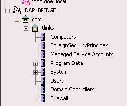
Select the "Object Management" tab and click on "Fetch Branches" tab, if the config is correct it will query the AD and display as below

Finally on the "Authentication" tab select "Checkpoint Password"

Once the bridge config is done, its visible under "Users and Administration" container. Right click and choose "Update tree" , its going to pull the entire AD content..


So this is how we link check point to LDAP server.

Monday, February 2, 2015
Checkpoint Lab - 10 (Building VPN tunnel) Tutorial
VPN Tunnel -
In this section lets see how to setup an IPSec VPN tunnel between Main Office and Branch Office. In order to setup a VPN connection between 2 systems we must cover the process and methods on what happens when VPN connections is established and how it works. The main purpose of establishing a VPN tunnel is to give users access to the resources @ either offices with out creating NAT's. (Its not always possible to create NAT's for example lets say a network admin who has access to all the server and workstations travels to branch office and then is called to work on an issue in main office, its not possible to put all the servers or work stations on NAT for him to access externally. So to make sure he has access to all resources same like when he is sitting in the main office Site to site VPN can be established). Once the user VPN's in or a VPN tunnel is established they can access 10.1.1.0 or 10.2.2.0 networks including the DMZ's as soon as the policies are created.To use any VPN technology the data packet between the 2 points need to be encrypted (DES, 3DES or AES) and the integrity of the data packet should be checked constantly (MD5, SHA) to determine the packet sent is actually the packet received.
Concept - Symmetrical key exchange
- The technology by which 2 devices use the same key to encrypt and decrypt the data packet. Content to generate and exchange must be done in secure fashion.
- Internet key exchange (IKE) is used to accomplish the above. (Version1, Version 2)
- Diffie-Hellman (DH) is the method that the symmetrical keys are built and exchanged.
IKE version1 - The VPN connection is setup in 2 phases.
Phase1 - Both the peers negotiate on the technologies they will use to set the connection, similar to SSL (article posted here)
They authenticate with each other using a pre shared key or a certificate.
Both the parties create a shared key that only either of them knows using DH.Using this key the subsequent data is exchanged.
At this point IKE Phase 1 tunnel is established between 2 end points.
This phase supports 2 modes
Main mode - Its the default mode where the IKE negotiation happens using 6 packets. This mode is less vulnerable to Dos attacks. DH computations is done after the auth is done unlike aggressive mode where both are done at same time.
Aggressive mode - It performs the IKE negotiation with three packets. (Config vai check box 13 images down - Advanced VPN Properties)
Phase2 - This kicks in when the client actually initiates the traffic. Like admin tries to connect to a server in main office.
Both the parties start a new negotiation based on the previous Phase1 negotiation (The encryption and hash values can be changed, need not be the same, we can use SHA and AES in phase2 if in phase1 we used MD5 and 3DES)
Symmetric IPSec keys are created using DH keys from phase1 and an IPSec tunnel is built for the bulk data exchange. Depending on the values selected it can be taxing on systems but hard to break and vice versa.
Checkpoint terminology for VPN
Mesh - When the requirement is to set up vpn tunnels between all the gateways so that they can talk to each other then its called Mesh topology.
Start or Hub and Spoke - When the requirement is setup a tunnel between One (Main Office) and multiple branches. The branch office can only communicate with the main office but not with each other.

VPN Community - The entire topology gateways, servers, routers, switches between which the tunnel is setup is called VPN community.
VPN Member - The gateway/Firewall from which the VPN connection will be configured is called VPN member.
VPN Domain - The network (excluding the gateway) is called VPN domain. For example 10.1.1.0 with server, DMZ, work stations, manager is called a VPN domain.
VPN Site - VPN Domain + VPN Member.

First thing to check and enable is the IPSec VPN blade on the gateways.

Next step is to define VPN domain. A gateway has multiple interfaces, we have an option of defining which subnet should be part of the VPN domain. Go to "Topology" option and for the VPN domain either choose all the interfaces or we can manually specify the interface which should be part of the domain. In the lab I am using the 10.X.X.X subnet so selected "Main_Internal_10.1.1.0" at main office and "Branch_Internal_10.2.2.0" at branch office.


Now a VPN community needs to be defined. So go to Smart Dash Board and select "IPSec VPN" tab.

We will setup Star or Hub and spoke community between the 2 lab gateways.

Because its hub and spoke select Main office gateway device as Center Gateways and Branch office device as Satellite Gateways by using "Add" button.


In the encryption options we can select what version of IKE to use, version 1 is selected by default (Usually version 2 is used with IPv6 and when you need to set up the site to site vpn tunnel with a non checkpoint device like Cisco or sonic wall version 2 is not supported).

Encryption Suite lets you define hash, encryption, DH algorithms...by default "Custom" is selected. As mentioned earlier the encryption can be different for phase1 and phase2 so I changed the phased 2 to AES-128 and SHA 256.

Tunnel management option lets you define how many VPN tunnels need to be opened between gateways - default value is "One VPN tunnel per subnet pair" so it uses one phase2 IPSec tunnel and let the whole subnet 10.1.1.0 and 10.2.2.0 talk.

Most important thing is to disable natting when you VPN in from one site to another because its not needed and if the user from site A connects to a resource in site B the source packet will be natted to the gateway and the resource will send the packet to the gateway.
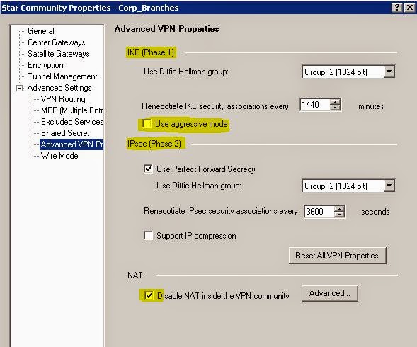
We can also specify the DH properties at phase1 and 2, renegotiate SA option (the more number of times that its negotiated and recreated the more secure, but overhead on resources is also more)

By following the above steps the new VPN community is setup.
Next thing to accomplish is to set up the policy for the flow of traffic. The VPN policy that need to be in place for the VPN communication to happen is below (Save and install the policy once created.)


Open the second key and you will see phase 2 tunnel build log.

Since we enabled Perfect Forward Secrecy (6 screen prints above) PFS, AES-128 and SHA 256 are displayed in the phase 2 negotiation. From the CLI perspective "vpn tu" can be used to look at the LKE and IPSec SA's. Go through all the options, try deleting the SA and initiate the ping requests and see how the communication happens.

This concludes the site to site VPN setup.
Friday, January 23, 2015
Checkpoint Lab - 9 (Policies and DB versions) Tutorial
Before we discuss the policies and db versions lets start expanding our lab a little bit. We will start working on the Branch Office setup and Branch Office DMZ configuration. Go ahead using the previously discussed steps in LAB-4. Set it up a Security Gateway/Firewall only for Branch Office. We will use the existing Manager to connect to both the firewalls (Main and Branch Office).
Assuming you are done installing the firewall and are ready to add it to the Manager, we first need to create rules for manager to access the branch Office firewall. To add it to the manager, this time we will use the wizard mode (Previously we used classic mode)

Once you select the Wiz mode you will see the screen below - Select the external ISP ip 10.100.100.253 and Gateway name appropriately.

Click "Next" and enter the one time password for the manager to establish SIC.

And as expected it will fail. The manager will not be able to connect since its in the internal Main office. For it to reach the branch office firewall we need to NAT the manager traffic to use an external ISP IP address. Refer the below screen print.

Double click the "Manager" object and in the NAT assign it a public ISP address, select MainOffice_Firewall on the install on gateway option and check the Apply for security gateway control connections. This option means use this NAT to manage any other firewalls via this manager.
Now try establishing the SIC communication again between the manager and the BR_Firewall with the NAT in place the devices will communicate and trust will be now established.
Earlier chapter covered how to create policy now lets try to create a consolidated policy that can be applied on multiple firewall gateway since its not feasible to maintain different policies for different firewall, it can be confusing and tedious. So below is the example on how to create single policy and push it to multiple gateways.
 The first management policy can be applied to all the firewall gateways in the company. So the destination would include both the firewalls. Same applies to the Stealth, Netbios and cleanup. The install on will actually decided which device the policy will be applied. If the "Install on" is "Policy Targets" it will be pushed to all the gateways. For targeted deployments just chose which device it needs to go to. Form the above above example - "Main Office rules3-4" will get pushed to MainOffice Firewall and "Branch Office Rules 5-6" will go to the Branch Office firewall. When the policy is pushed you will be presented with both the devices selected and we can opt out at this point as well to where the policy goes.

Don't forget to dynamically NAT the inside traffic going external for both Main and Branch internal networks. You can select option "Hide behind gateway". Choose the appropriate firewall device on with this will be deployed as well.

Now lets take a look at the DMZ policies that were implemented as per our lab setup. Assumption - DMZ servers at both sites will be running web and ftp services. First the DMZ server objects needs to be defined as Nodes.


And we are enabling a static NAT to a public IP - 10.100.100.205, the ip that can be accessed from "outside" the network by clients. This would add the NAT rule automatically -

Outbound -
Original Pkt - Source - DMZ server (172.16.1.2) , Destination - Any, Service - Any
Translated as - Source - DMZ server NAT ip (10.100.100.205), Destination - Same as Original pkt, Service - Any
So when the server initiates outbound connection like a response to client 1.2.3.4, the packet inside the DMZ network before it hot the firewall would be
Src - 172.16.1.2, Client - 1.2.3.4, Port 80
and when it leaves the firewall interface that packet will be modified as
Src - 10.100.100.205, Client - 1.2.3.4, Port 80
This way the client cal talk back to the 10.100.100.205 ip since it does not know the private DMZ ip 172.16.1.2
Inbound -
Original Pkt - Source - Any , Destination - DMZ server (172.16.1.2), Service - Any
Translated as Source - Same as Original pkt, Destination - DMZ server NAT ip (10.100.100.205), Service - Any
Same rule applies for an inbound connection as well. When a client 1.2.3.4 connect to DMZ server to consume ftp service, before the packet hits the firewall -
Src - 1.2.3.4, Client - 10.100.100.205, Port 21
After it hits the firewall -
Src - 1.2.3.4, Client - 172.16.1.2, Port 21
The red S symbol implies that the object has a Static NAT, Similarly H implies its a hide NAT.Now we create the policy as below where we specify the services and on what firewall that this rule must be applied.

Similarly configure the branch office DMZ server and group the Common (go on both), Main office - HQ_Firewall, Branch - BR_Firewall and you should have something like below -


Once you hit "OK" a backup is created and stored in the database of the manager. To view options of the backups, go to File--> Database Revision Control option. I created multiple backups when building the lab and it looks like below -

There are diff options you can configure
You can rotate/restrict the number of backups that are saved on the system.
Select "Automatically delete old versions - Configure" tab

Multiple options are available on how the versions can be retained. Since this is a lab setup I choose 10 options. It also depends on how much disk space was allocated during the initial install.
If you want to lock on to a backup which you know is good and can fall back to
it as safety net you might want to mark that as "don't delete" copy. Select the db version and click "Properties" tab and choose - "Keep this version from being deleted automatically." This options will display a crossed trash can which visually indicates that it will not be deleted when the version deletes happen.

The restore can be done by clicking "Action" and selecting the "Restore Version"...since its a lab setup...try deleting few objects and rules and use this option to check if the deleted items are restored correctly. "Remove Keep" will negate the "Keep this version" option and will enable the policy to be deleted. "View version" will open that version in a new dashboard instance.

Assuming you are done installing the firewall and are ready to add it to the Manager, we first need to create rules for manager to access the branch Office firewall. To add it to the manager, this time we will use the wizard mode (Previously we used classic mode)
Once you select the Wiz mode you will see the screen below - Select the external ISP ip 10.100.100.253 and Gateway name appropriately.
Click "Next" and enter the one time password for the manager to establish SIC.
And as expected it will fail. The manager will not be able to connect since its in the internal Main office. For it to reach the branch office firewall we need to NAT the manager traffic to use an external ISP IP address. Refer the below screen print.
Double click the "Manager" object and in the NAT assign it a public ISP address, select MainOffice_Firewall on the install on gateway option and check the Apply for security gateway control connections. This option means use this NAT to manage any other firewalls via this manager.
Now try establishing the SIC communication again between the manager and the BR_Firewall with the NAT in place the devices will communicate and trust will be now established.
Earlier chapter covered how to create policy now lets try to create a consolidated policy that can be applied on multiple firewall gateway since its not feasible to maintain different policies for different firewall, it can be confusing and tedious. So below is the example on how to create single policy and push it to multiple gateways.
Now lets take a look at the DMZ policies that were implemented as per our lab setup. Assumption - DMZ servers at both sites will be running web and ftp services. First the DMZ server objects needs to be defined as Nodes.
The DMZ server at MAin office DMZ - 172.16.1.2
And we are enabling a static NAT to a public IP - 10.100.100.205, the ip that can be accessed from "outside" the network by clients. This would add the NAT rule automatically -
Outbound -
Original Pkt - Source - DMZ server (172.16.1.2) , Destination - Any, Service - Any
Translated as - Source - DMZ server NAT ip (10.100.100.205), Destination - Same as Original pkt, Service - Any
So when the server initiates outbound connection like a response to client 1.2.3.4, the packet inside the DMZ network before it hot the firewall would be
Src - 172.16.1.2, Client - 1.2.3.4, Port 80
and when it leaves the firewall interface that packet will be modified as
Src - 10.100.100.205, Client - 1.2.3.4, Port 80
This way the client cal talk back to the 10.100.100.205 ip since it does not know the private DMZ ip 172.16.1.2
Inbound -
Original Pkt - Source - Any , Destination - DMZ server (172.16.1.2), Service - Any
Translated as Source - Same as Original pkt, Destination - DMZ server NAT ip (10.100.100.205), Service - Any
Same rule applies for an inbound connection as well. When a client 1.2.3.4 connect to DMZ server to consume ftp service, before the packet hits the firewall -
Src - 1.2.3.4, Client - 10.100.100.205, Port 21
After it hits the firewall -
Src - 1.2.3.4, Client - 172.16.1.2, Port 21
The red S symbol implies that the object has a Static NAT, Similarly H implies its a hide NAT.Now we create the policy as below where we specify the services and on what firewall that this rule must be applied.
Similarly configure the branch office DMZ server and group the Common (go on both), Main office - HQ_Firewall, Branch - BR_Firewall and you should have something like below -
Database -
Checkpoint gave admin's a great option to backup the policies and objects that are created. This options is presented when the policies are being installed on the gateways. By giving the option to backup we can take easily recover when a bad policy is deployed and cause an outage. Using the previously taken backup we can restore in matter of min and then investigate what happened with the bad policy at leisure.
Once you hit "OK" a backup is created and stored in the database of the manager. To view options of the backups, go to File--> Database Revision Control option. I created multiple backups when building the lab and it looks like below -
There are diff options you can configure
You can rotate/restrict the number of backups that are saved on the system.
Select "Automatically delete old versions - Configure" tab
Multiple options are available on how the versions can be retained. Since this is a lab setup I choose 10 options. It also depends on how much disk space was allocated during the initial install.
If you want to lock on to a backup which you know is good and can fall back to
it as safety net you might want to mark that as "don't delete" copy. Select the db version and click "Properties" tab and choose - "Keep this version from being deleted automatically." This options will display a crossed trash can which visually indicates that it will not be deleted when the version deletes happen.
The restore can be done by clicking "Action" and selecting the "Restore Version"...since its a lab setup...try deleting few objects and rules and use this option to check if the deleted items are restored correctly. "Remove Keep" will negate the "Keep this version" option and will enable the policy to be deleted. "View version" will open that version in a new dashboard instance.
Subscribe to:
Posts (Atom)